Simulation of nucleation and cracks propagation by GFEM
Simulation of nucleation and cracks propagation by GFEM
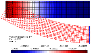
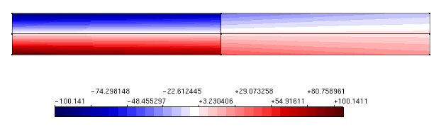
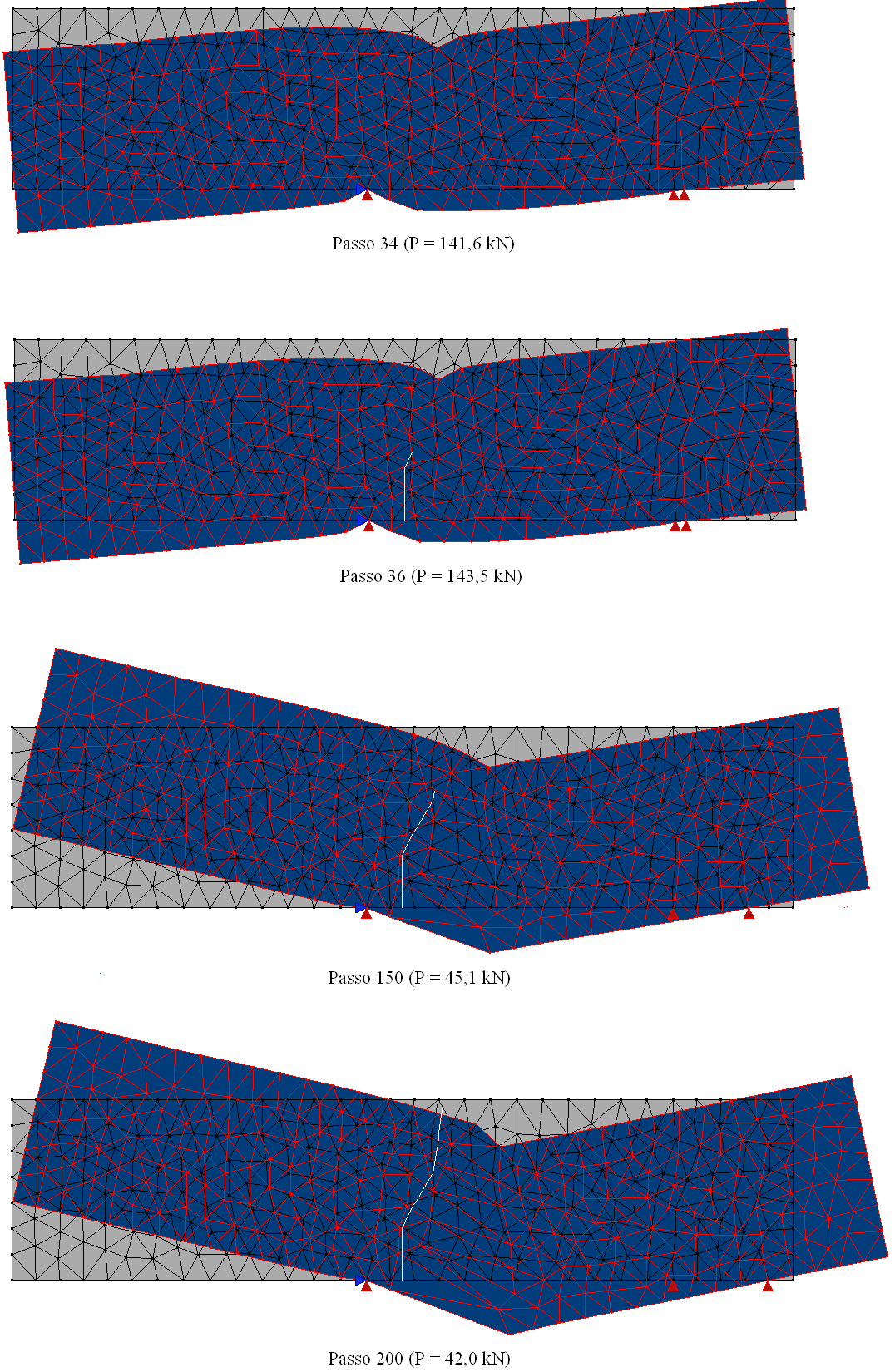
Aiming to reproduce numerically the four point shear test performed by Arrea and Ingraffea (1982), shown in Figure 1, the INSANE system was adopted, using the theoretical-computational framework to simulate the process of nucleation and discrete cracks propagation, developed by Silva (2016). Constitutive model of fixed smeared crack with Carreira and Chu (1985) law for compression and Boone et al. (1986) law for tension was adopted in the modeling. The material parameters are: modulus of elasticity E0 = 24800.0 N/mm2, Poisson ratio ν = 0.18, compressive strength fc = 34.0 N/mm2, tensile strength ft = 3.4 N/mm2, strain relative to the elastic limit in compression εc = 0.002, fracture energy Gf = 0.120 N/mm, characteristic length h = 40 mm and shear retention factor βr = 0.02. The beam was modeled with triangular elements of three nodes T3 in plane stress. The preexisting failure was modeled as a notch, by means of a resource available in the system in charge of enriching the necessary nodes for simulation of the jump in the displacements field. The direct displacement control method was used in the solution of the model, increasing the degree of freedom added to one of the nodes of the edge containing the “mouth” of the notch by 0.00065 mm. This degree of freedom refers to a portion of the relative tangential sliding of this “mouth”, i.e., a portion of the Crack Mouth Sliding Displacement (CMSD) was controlled, with tolerance for convergence of 1 x 10⁻³ and reference load P = 130000.0 N. The equilibrium path of the crack mouth sliding displacement (CMSD) is shown in the Figure 2, compared to the experimental results of Arrea and Ingraffea (1982) and numerical results of Fang et al. (2008), which in turn analyzed the beam with a constitutive model of cohesive crack that adopts bilinear and exponential laws in a model of extended finite elements. Figures 3 and 4 show, respectively, the deformed with scale factor equal to 500 and the shear stress τxy along the domain to the steps 34 (141.6 kN), 36 (143.5 kN), 150 (45.1 kN) and 200 (42.0 kN).
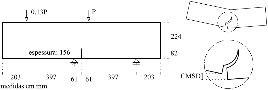
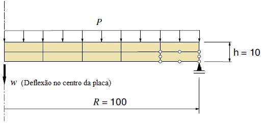
Figure 1 – Geometry
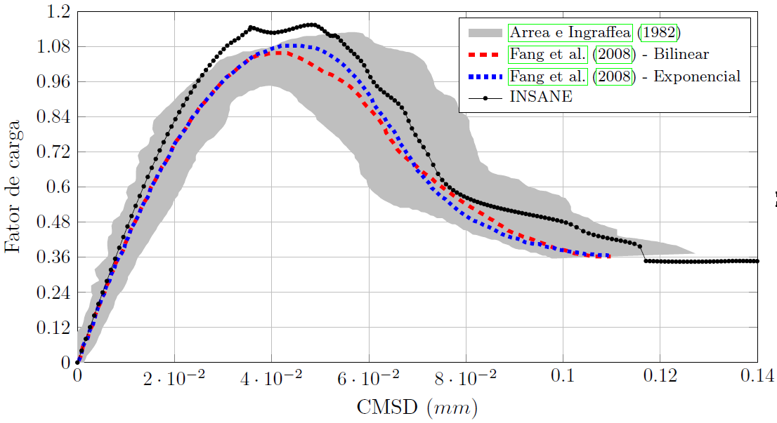
Figure 2 – Curves CMSD x load factor
Figure 3 – Deformed state
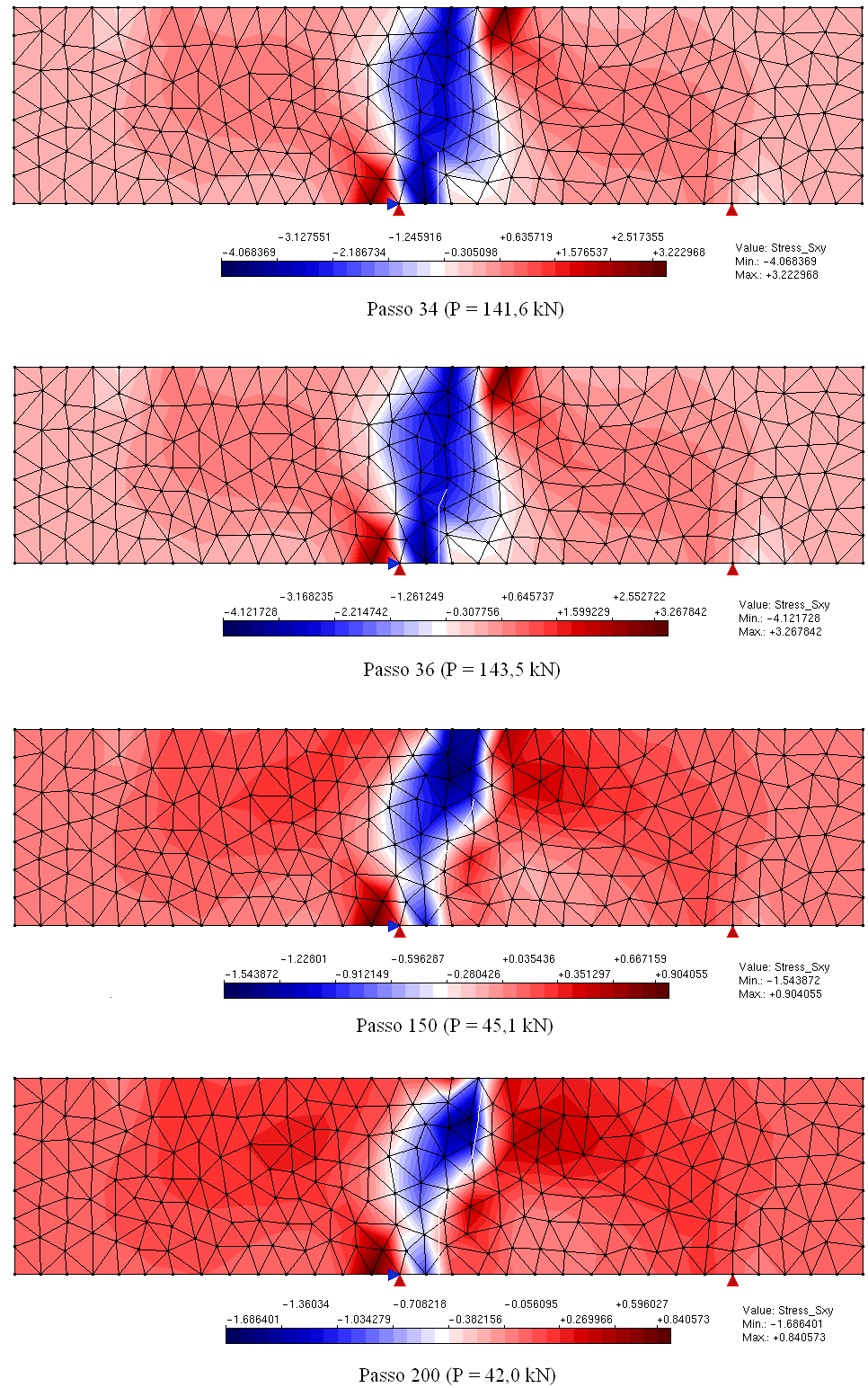
Figure 4 – Shear stress τxy
References
- Arrea, M. e Ingraffea, A., 1982. Mixed mode crack propagation in mortar and concrete. Technical report 81-13, Departement of Structural Engineering, Cornell University, Ithaca, EUA. Cited by Rots et al. (1985).
- Boone, T., Wawrzynek, P. A. e Ingraffea, A. R., 1986. ‘Simulation of the fracture process in rock with application to hydrofracturing’. International Journal of Rock Mechanics and Minig Science, vol. 23 (3), pp. 255-265.
- Carreira, D. J. e Chu, K., 1985. ‘Stress-strain relationship for plain concrete in compression’. ACI Journal, vol. 82, pp. 797-804.
- Fang, X.-J., Jin, F. e Yang, Q.-D., 2008. ‘Extended finite-element analysis of fractures in concrete’. Engineering and Computational Mechanics, vol. 161, pp. 187-197.
- Rots, J. G., Nauta, P., Kusters, G. M. e Blaauwendrra, J., 1985. ‘Smeared crack approach and fracture localization in concrete’. HERON 30, vol. (1), pp. 1-48.
- Silva, L. L., 2016. Sistema gráfico interativo para análise de nucleação e propagação de trincas. Master thesis, Universidade Federal de Minas Gerais, Belo Horizonte, MG, Brazil.